Saturday, 24 October 2015

Macchi C.205 'Veltro' - (1:48 Tauro Model) Part 7

Painting the Engine


Tools and Materials Used

  • Mr Surfacer 1200 primer
  • Alclad II Steel
  • Alclad II Aluminium
  • Vallejo Model Color 70.950 Black
  • Vallejo Model Color 70.820 Offwhite
  • Vallejo Model Color 70.871 Leather brown
  • AK-086 Dark Steel pigment
  • AK-043 Medium Rust pigment
  • Citadel color Boltgun Metal
  • Citadel color Mephiston Red
  • Black oil colour
  • Thin round brush
  • Old ruffled thin brush
  • White Spirit

The engine is first primed with Mr Surfacer 1200 applied with an airbrush.  Once dry a thin layer of gloss black is applied to serve as a base coat for the subsequent application of Alclad II Steel.

The engine block was then painted using a thin mix of black and white Vallejo acrylics by brush. The thinned paint is slightly translucent leaving some of the metallic sheen underneath to show through.  The exhaust stacks and most of the plumbing is not painted over.


Next, I apply some AK-086 Dark Steel pigment using an old brush.  I apply the pigment to the areas between the engine detail avoiding the recesses to create a sense of depth.  Using the same brush I apply some AK-043 Medium rust pigment to the exhaust stacks.


Plumbing and engine detail is picked off using Citadel Boltgun Metal


Some of the plumbing is painted with a red-brown mix using Citadel and Vallejo acrylics.


The engine brackets are primed using Mr Surfacer followed by some Gloss Black.  They were then painted over using Alclad II Aluminium.


A black wash is obtained by diluting some black oil colour with white spirit.  The wash was generously applied to the brackets.


After a few moments, the excess is wiped off using a paper towel.


Wednesday, 9 September 2015

Arado Ar 234 "Blitz" (Hobbycraft 1:48) Part 3

The Cockpit (cont)


In Part 3 of this series of posts on the Arado Ar 234 build, we will take a look at the aircraft’s instrument panel and how it has been detailed to add more interest to the cockpit.

As explained in Part 2, the Arado’s glazed nose section exposes a lot of cockpit detail that would normally be hidden in other aircraft.  This is particularly true for the instrument panel, where all of its wiring and supporting structure is clearly visible.

The front of the instrument panel has been detailed using an aftermarket photo-etched part which has much crisper detail than the kit part itself.  On the other hand, the detail on the back has been scratch-built using various bits of copper wire and plastic.

Let’s take a closer look at the process.

Preparation

The first task is to clean the kit part, removing all detail from both sides of the panel using a small file.   

Filing off the kit detail
The photo-etch instrument bezels are then glued to the cleaned-up plastic panel.  At this point it was very apparent that the plastic panel is actually larger than it’s supposed to be, probably because of the way the kit is meant to go together.    Given that I was going to add the supporting structure as found on the real aircraft, I could trim the panel down to size using the photo-etched part as a guide.

That’s all there is to it with respect to the front of the panel.  We will now have a look at the much more interesting process of detailing the back. 

Wiring Up

The first step is to glue in place the individual instrument backs which were made using ‘slices’ of plastic rod.  Rods of different diameters were used to represent the different instrument sizes.

Adding the instrument 'backs'

At this stage I also bent some wire into the proper shape and glued it to the instrument panel.  This will help me handle the instrument panel better and will eventually become its the bottom support frame.

All instrument 'backs' in place 
The instruments are then drilled out using a twist-drill in preparation for wiring.  Slotting and gluing the copper wire strands into these holes will help create a stronger bond and makes bending the wires into shape that much easier.
Adding the wiring loom

Rest of the wires are added, ready to be bent into shape

The wires are then bent into shape and trimmed to the required length.

The finished wiring

The instrument panel from the front.
At this point the wire acting as the support frame is cut and bent into shape and the whole assembly is test-fitted to the rest of the cockpit:

Test fitting the instrument panel
The assembly as seen from the front

Adding the rest of the supports

On the real aircraft, the instrument panel is supported from the top and back by a tubular structure which connects to the rest of the nose framing.  Getting the angles right in such a situation can be tricky so as a starting point I plot out the instrument panel position with respect to the ‘canopy’ as shown below.  This was done by dry-fitting the panel to the cockpit and securing the canopy in place with some masking tape.  I then measured the distances using a flexible rule.

Plotting the instrument panel position with respect to the 'canopy'
The first bit of wire is bent to shape using the template as a guide.  It is important to get the angles right at this stage and any extra length of wire can be trimmed later.


The second length of wire is added and both are secured to the template using some masking tape as shown below:


Securing the wire with masking tape

Finally I add a tiny drop of superglue with the help of another bit of wire, just enough to bond the two parts of the structure together.  This the most delicate part of the process as putting too much glue will fix the whole assembly to the paper template.

This process was repeated once more to create two identical assemblies which are then glued in place at the back of the instrument panel.

Finally, the whole assembly is once more test fitted in place to check out the dimensions and trim any excess.


That concludes todays post which focused on adding detail to the instrument panel which is a very prominent feature in Arado Ar 234’s cockpit.

Part 4 will focus on the other end of the cockpit specifically the seat and bulkhead and hopefully conclude the chapter on the cockpit.  I’m treating the canopy itself, with its intricate framing, as a separate project and will be tackled in future posts.

In the meantime Happy Modelling.

Saturday, 5 September 2015

Arado Ar 234 "Blitz" (Hobbycraft 1:48) Part 2

The Cockpit

One of the Arado 234's striking characteristics is its completely glazed nose which exposes much more cockpit detail than would normally be seen on more 'conventional' aircraft.

In my previous post I had promised myself (and anyone reading for that matter) that this would be a straight-forward, no-frills build but after looking at a number of photos of the last surviving Ar 234 I just could not help myself - that cockpit begs to be detailed.


Preparation

As previously mentioned, I had a number of aftermarket detail parts for this kit, a fair number of which are resin.  This is especially true for the cockpit as the entire cockpit tub, detail and rear bulkhead are resin parts, so the first thing to do was to clean the various bits.

Quick Tip
Resin dust is hazardous for the lungs.  Make sure to wear a protective mask when sanding, cutting, drilling and cleaning resin parts and clean your work-space when you're done.  You may find it convenient to work on all the resin bits in one go.

The Cockpit Tub

After preparing all the resin, I started working on the cockpit tub.  I needed to use the rudder pedal supports from the original kit part so they were sawed off using the same micro-saws used to cut out the wing control surfaces as shown in part 1 of this series.

Removing the original rudder pedal supports
These were then glued to the resin cockpit floor using super glue.

Transplant complete
Once dry I proceeded to add the photo-etch rudder pedals which are much nicer than the plastic parts that come with the kit.  These were bent into shape with the help of some tweezers and fixed in place using super glue.

The rudder pedals are fixed in place
Quick Tip


Use a sharp round edge of a number 10 blade to separate photo etch parts from their fret.  Make sure to cut on a hard surface such as a metal block to prevent the fret from bending when you apply pressure.  Try to be as precise as you can and cut as close to the part as possible as filing away any extra bits can be tricky.

I then tackled the control column which was also supplied in resin and is much more accurate than it's plastic counterpart.  The aftermarket control column came in two parts, the column itself and the handlebars.  I wasn't happy with the detail on the handle bars - which is another way of saying I broke them whilst cleaning off all the flash - so I fashioned my own using some copper wire.  You can see the result next to the original kit part in the image below:

Comparing the control columns, resin (and copper) part on the left, plastic on the right
Control column in place

Preparing for the instrument panel

The instrument panel on the Ar 234 is held in place by a number of supports, two of which come out from a "U" shaped panel on the front of the cockpit tub.  The kit instructions would have you glue the instrument panel directly to the canopy... something I would like to avoid because a) it's not accurate and b) it just would not look right.  First off the "U" panel...

The following sequence of photographs shows how this was fashioned out of plastic-card:

Marking the cross-section using lower half of glazed nose

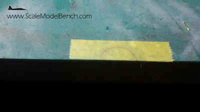
The marked cross-section on strip of masking tape

Cross section cut out and tape transferred to plastic sheet

The cut panel

The finished item

Here's a shot of the panel, fixed in place and drilled in preparation for the instrument panel supports. The gap seen on the left is due to the cockpit tub shifting whilst taking the photo. 
I also added some wiring detail to the rudder pedals.

"U" Panel added to the cockpit

Coming next...

In the next post I will tackle the fiddly instrument panel itself, including the scratch built wiring and supports.

Saturday, 29 August 2015

Arado Ar 234 "Blitz" (Hobbycraft 1:48)

Box Cover
The Arado Ar-234 holds a special place in aviation history by being the first ever operational jet bomber.  I have always been fascinated by its sleek design as well as the engineering behind it and I've always wanted to build a scale model of the "Blitz".

I will be presenting this build in parallel with the Macchi C.205 which I have been writing about so far.  In contrast to the high-detail Macchi build, this build will be relatively straight forward and will only use aftermarket components to improve/enhance the model.

The kit is from HobbyCraft and hails from 1989.  I picked this up from a friend who had already bought a ton of aftermarket resin parts to improve the model.

Box Contents

The box contents
   The image above shows the box contents, including the aftermarket parts which had been bought by the previous owner of the kit.  These include:
  • Metal undercarriage legs and resin wheels;
  • Photo-etch fret with canopy and cockpit detail;
  • Resin cockpit detail;
  • Resin wing control surfaces, and;
  • Resin engine intakes.
The surface detail on the plastic parts is pretty good considering the kit's 26 years of age.  Panel lines are recessed and crisp, the parts are flash free and the fit is surprisingly good. All bodes well for a relatively straightforward build.

Preparing the Wings

The first task I chose to tackle was to prepare the wings to accept the resin control surfaces.  This meant cutting out the kit's control surfaces from the wings to make way for the resin replacements.

Sawing off the existing control surfaces.
To do this I used a number of micro-saws specifically designed for this kind of job.  Using the panel lines as a guide, I gently ran the saw across the wing surface around the control surfaces.

Once the first wing half is done, I check it against its counterpart to ensure that the panel lines match up.

Checking that the panel lines align before cutting  
Thankfully the panels did align on the four wing halves and the same process was repeated until all the kit control-surfaces were hacked off.

Test-fitting the resin control surfaces
Before gluing the wing halves together I drill holes for the engine mounting points:

Drilling the engine mounting holes

I then proceeded to test fit the engines to the wings and the wings to the fuselage:

Test fitting engines, wings and fuselage

 Next Steps

The next step will be tackling the cockpit area by preparing the supplied resin parts and test fitting everything to the fuselage.

This is turning out to be quite an enjoyable build, the kit has aged well and the aftermarket parts are just one big bonus.

Stay tuned for more on both the "Blitz" and the Macchi.  Thanks for watching and please drop a line if you have any suggestions on how I can improve the content of these posts.

Also in this series

Monday, 24 August 2015

Macchi C.205 'Veltro' - (1:48 Tauro Model) Part 6

The Benefits of Dry-Fitting

Those of you following this series may recall that my next post was going to deal with painting the engine and the various scratch built bits, however plans in scale modelling are there to be disregarded and thrown out the proverbial window.

Before heading off to paint I always dedicate some time to dry-fitting the various bits and pieces to make sure everything fits.  This gives me the chance to alter things before committing to paint.  This is especially true when there is a lot of scratch-built detail involved and the original fit of the kit leaves a lot to be desired.  In fact as I was test fitting the cockpit floor to the fuselage I came to realise that the seat would be almost a full cm further back than it should be.  The mounting points supplied are simply too far back, in fact the seat would be sitting inside the fuselage almost hidden from view!

Choices

Now the supplied mounting points are just bits of plastic protruding from the cockpit floor and are nothing like the real thing.  At first I wasn't that concerned with them as they would be hidden below the seat and would be practically invisible.

At this point I had a choice, either re-position them further forward or go the whole nine yards and scratch-build some new mounts.  The perfectionist in me got the better of me and I gave in to the second option.

The following sequence of photographs illustrate the process

Preparing the Frame
Preparing the legs
Fixing the legs and support struts
Fixing the seat to the frame
A view of the seat from the side
Test fitting the seat.  The yellow arrow points to the original seat position

I could have simply gone for a re-positioning of the original mounts but in the end, the new frame only took around an hour to make (including time for the glue to set) and I think it adds a bit more character and authenticity to the cockpit.  

I am now toying with the idea of adding the oxygen tanks, which sit right behind the pilot's seat, to fill the visible empty space.  Stay tuned ...


Friday, 21 August 2015

Macchi C.205 'Veltro' - (1:48 Tauro Model) Part 5

Detailing the Engine (cont)

Welcome back.

In my last post I described the process for creating the scratch-built gun bay access panels.  I also mentioned that the gun bays would be left open, showing the detail inside.  The kit does provide the two Breda-SAFAT 12.7mm machine guns, however the quality of the parts is rather poor, especially the gun barrels. I therefore decided to replace these with some brass items from Master-Model.  

Until these arrive I will put the gun-bay project on hold and shift my focus back to the engine bay detail, specifically adding the Oil and Engine Coolant lines.

We will first start by having a look at the tools and materials used.

Tools and Materials Used


  • Copper Wire - various thicknesses up to 0.5mm
  • Plastic Rods
  • Superglue
  • Pin vise with 0.25mm drill bit
  • Tweezers
  • Good Reference Diagrams

Preparing the Hoses

Reference photographs of the wheel wells clearly show quite a number of flexible pipes of different widths going to and from the engine.

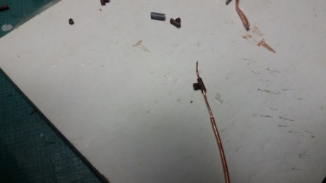
To make these hoses I coil a strand of the thinnest copper wire I can find (approx 0.25mm) and wind it round a strand of thicker copper wire creating a coil.  By combining wires of different thicknesses I prepare a number of different hoses ready to be used as necessary.

Creating a hose

Assorted hoses

The Engine Cooling System

The engine cooling system can be divided into two sections:
  • The reservoir and pipes leading to the engine 
  • The pipes leading from the engine to the radiator and back.
The above are situated at the top and bottom of the engine bay respectively.  Starting from the top, the coolant reservoir has four, relatively thin pipes running to the engine.  I take the thinnest coil there is from the set I prepared earlier, cut four separate strands and glue them to the tank.  Drilling the tank using a pin-vise and inserting the wire into these holes provides both a better bond and better look:

Attaching the pipes to the tank
 The wires are kept rather long on purpose.  These will be cut to size later on in the build. 

Test fitting the assembly to the firewall...

... and engine

 I also glued thin strips of aluminium to the pipes to simulate fastening clips.

 The rest of the plumbing is simpler as it only consists of a couple of thicker pipes coming through the firewall and under the engine.  These can simply be cut to size and positioned once the engine is installed.

The Oil Cooling system

The oil cooling system is slightly more complex, involving even more pipes and fittings.  A quick look at our reference diagram reveals a number of "T" joints in the system which I decided to tackle first.

Using a 0.25mm twist drill I drill holes down the centre of a plastic rod, as far as I can go whilst keeping to the centre as much as possible. This is then cut to the required lengths and the copper wire is passed through. 

The following sequence of photos illustrate this process:

Drilling the plastic rod

Passing a copper wire through the drilled hole

Gluing a shorter section of hollowed plastic to form the "T"

Another view of the "T"


The finished items
The next step is adding lines from the oil tank, leaving any excess as necessary.


The oil tank is then test-fitted to the firewall:
Test fitting the oil tank
Finally, I add more pipes to the system, starting from the "T" s that were created earlier.


It is now evident that the entire plumbing system will have to be painted separately before assembly as it would be nigh impossible to do so otherwise.  Furthermore, the excess length of the piping can only be trimmed to size once the engine is securely installed i.e. after it is painted.

Next Steps

Even though reference photos show even more wiring, it would be foolish to attempt to add these now.  The model has come to a stage where things need to be glued into place to see what (if any) space will remain for any extra detail.  This is especially true for the top area of the engine bay where the engine coolant tank sits between the machine gun barrels.  I need to make sure that there is enough space for the new brass items to fit properly.

Final Words

I would like to finish off by thanking all those who have visited this little corner of the web so far.  Please feel free to leave your comments, especially feedback on how I can improve these posts.

Until next time...